Your Legal Resource
My Earlier Tube Type Guitar Amp Projects
My Earlier Tube Type Guitar Amp Projects
2005 Robert B. Richards, All rights reserved.
Short Description:
The aqua amp head on the left is my version of the Octal Fatness amp, which I call the Fat Mama. A 6SJ7 pentode driving a 12AX7 distortion generating stage driving tone and master vol and then the 6V6 single-ended output stage. The speaker is a Celestion Vintage 30, 12 inches, in a cabinet I built. It has a warm but solid sound and very good sounding distortion. I changed the tone circuit (much improved over Octal Fatness design), added a line out circuit, Rf filtering at the input and at the AC line, DC on the filaments, very filtered B+ but still with the proper "sag" R/C in the right place, and low noise metal film resistors in the front end. The little "TV front" tweed amp on the right is another variation of the Octal Fatness circuit using a 12AX7 front end, a 12AX7 distorting middle section, then a tone section that is similar to the 1957 Fender e-type tone but has only Bass and Treble. It's designed to be used at home as a practice amp, or as a great distortion generating preamp in a bigger system. It makes a great supplement to another amp when you have a stereo reverb pedal or equivalent. Both amps have conditioned and variable Line Outs for use in whatever situation where that could be useful. The Line Outs are taken right off the speaker, RF filtered, resistively attenuated. If this ground is lifted, there would be no possible ground loop situation when using it to drive a bigger amp. (I forgot when I wired it - I'll have to fix that).
From the guy who bought my Fat Mama Amp:
Hi Rob
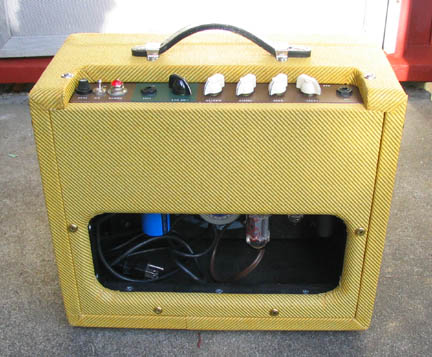
Really loving the amp. Darka, my wife loves it too! Especially dialed up and rockin' (difficult to resist doing since the distortion sounds so good). Jammed with some guys, took the line-out into a little solid-state Fender amp. Couldn't believe how good it sounded. So I'll keep it in its' own box for portability. Got a fistful of NOS 6sj7s from a friend who found boxes full of tubes at a garage sale, GE and Sylvania. The attached photo is of my homebuilt amp. The Fat Mama now sits on top. Talk to you soon. Miri
And then a few months later from the same guy:
"Hi Rob
It's Miri, the guy who bought your aqua amp head. I hope you're well and doing good. Thought I'd drop you a line to let you know how much I'm still enjoying the amp. I've since played through a number of excellent guitar amps, and I have to say, yours really stands up for itself, it's really hard to beat. It never disappoints. Everybody who hears it is blown away by the beautiful tone. So thank you for building such a great beast. Hope you are continuing your sonic adventures."
Miri
Purpose of the project:
I've been designing and building audio electronic circuits for over 25 years, but I never really did much with tubes. I have a friend (Matt Kamna) who is a tube guru who I've known since 1978 when I first started working at Tektronix. Matt has been telling me for years that tubes sound better than transistors. Since I like to play guitar once in a while, I thought it would be fun to have a vintage-looking awesome sounding little guitar amp. When it comes to generating distortion for a guitar, I've never heard any solid-state amps sound nearly as good as when it's done with tubes, so... With Matt available as a consultant, I thought I should try my hand at it. Ultimately, I had to figure out which distortions sounded good and why, and then figure out how to deliver that in just the right way.
I'm not really much into distortion per se, but if it's really well-voiced distortion, I figured it could be fun for those occasional Eric Clapton/Muddy Waters/Elmore James style bluesy jams. There was the challenge aspect as well. I thought I knew how to do a tube amp better than most, in theory, but hadn't actually done it. I thought it would be easy to get great-sounding distortion. I found that it's more complicated than I thought. Operating tubes in the overdrive mode opens several "cans of worms" that aren't particularly well documented anywhere. This project proved to be a substantial challenge to my creativity and ingenuity. I re-built the first version five times, each time trying different topologies and distortion generating techniques. When I heard the Octal Fatness amp at Youtube on my computer, sound clips from the website of the "Octal Fatness" circuit, apparently designed by David Jones, Doug Hammond, and then modified by Paul Morossy, it hit me that I had found the version of distortion that I like. As I said, I'm not really a huge fan of distortion per se. I hardly ever use distortion, but when I do, it's got to be the good stuff.
I built one Octal Fatness circuit as a reference. Then I tried to do better.
How to get the perfect distortion (Zat is ze qvestion):
I found out the hard way that getting a really good-sounding distortion isn't easy. It takes a complex mixture of various distortion mechanisms all working together in just the right way to create the good stuff. I like when it gradually increases with signal level. A fast roll off of higher-order harmonics makes distortion more "musical" and less "noisy" sounding. Avoiding feedback is important for this. And then there's the way the output tube reacts to the output transformer and speaker reactance. And of course, there's the speaker/cabinet acoustic mechanism. A non-ribbed speaker cone breaks up sooner and more gradually and adds a real nice sound to anything bluesy.
I once went to a piano and played the notes that represented the even and odd harmonics relative to a fundamental frequency (which is technically called the first harmonic in engineering land - not sure why), to see which were pleasantly musically related to the fundamental frequency and its first few harmonics. The second harmonic is the same note one octave higher. Always an enhancement. The third harmonic distortion product forms a major chord with either the first harmonic (the fundamental) or the second harmonic. Fine unless the song is in a minor key. After that, it was hit and miss as to whether the distortion product would be musically desirable. More generation of the higher-order harmonics means an accumulation of energies that are not musically pleasantly related to the fundamental. The higher-order harmonics sound like noise and fizzle that seems to change little with stimulation frequency. I don't like the sound of the higher harmonics much. Heavy metal guys might like that. I figured that having bandwidth limiting after the distortion mechanism would be the way to go, I thought the game was that simple. Five rebuilds later I have more "wisdom". That original chassis is now in the graveyard. It sounded good, just not great.
The Octal Fatness Circuit:
In the Octal Fatness circuit, the front end 6SJ7 pentode gives you a very large amount of gain and generates a distortion spectrum that has a dominant 2nd harmonic product and some I.M. distortion. The waveshape is a little asymmetric (a good thing for guitar). The pentode drives the input level volume control. That signal goes into the 12AX7 second gain stage which can be independently overdriven to whatever extent is desired since there is also a Master volume after it. So there's a 12AX7 triode gain stage followed by a direct-coupled cathode-follower buffer, then a "tone-stack", and then a "master" volume control. This 12AX7 dual triode section distortion is mostly even-harmonic as it goes into distortion. Both the positive and negative half-cycles get clipped by a saturation characteristic, due to the direct-coupled follower going positive on its grid at high positive swings of the first triode of the pair. The output stage of a push-pull amp with matched tubes and driven with an exactly balanced drive would be likely to generate a distortion that would be dominated by odd distortion products. Especially if it had distortion "correcting" negative feedback. That's less desirable. This amp has a single-ended output stage, so would be highly likely to generate mostly even harmonic distortion. No matter how hard you drive this output stage, it never gets very symmetrical in the way it clips or the waveforms it produces. Because of the total lack of feedback, the distortion products don't extend out from the fundamental frequency nearly as far, as amplitude is increased.
History:
I'm completely convinced that good-sounding distortion was found by accident, back in the late 1940s and 1950s, and not appreciated by many musicians or record buyers as a desirable sound for several years. I've researched this extensively, both on the web (which is mostly bullshit) and on the bench. In the 1940s, it's well documented that Fender and the others barely knew how to design an amp at all. The very first oscilloscopes that were at all accurate came out in about 1947 from Tektronix. It was stated that the "engineers" all went to the RCA tube manual for circuit topologies and design methods, and then some played with various ways to adjust the tone. There wasn't much other engineering documentation to refer to, so much of the engineering process was done by ear. In those days everyone was a pioneer.
They claim that distortion was never a design goal back then. They were all trying to make the cleanest amp they could for as cheap as possible. It wasn't until the late 1950s that "distortion" became seriously popular, with people like Link Wray poking holes in the speaker cone to get an even more distorted sound. The 6SJ7 front-end pentode was apparently the tube to use in that day (also used in these amps), but it's a bit microphonic (like most other pentodes). In the early-mid 1950s, the 12AX7 triode came in to replace the 6SJ7 (and other similar octal tubes) since it was significantly less microphonic and more reliable overall. The 12AX7 provides a somewhat clean high gain but has a different sound than the 6SJ7. The blues amplifiers Fender is putting out now (2006) use 12AX7's in both the front end and the middle distorting stages. Better reliability and lower costs. Not necessarily better sound.
The first Fender tweed amp, the Dual Professional, from 1946:
This is the first Fender tweed amp, the Dual Professional (1946). You can see the speaker board sound hole cutouts by the staining of the grill cloth. A "coloring" mechanism in itself. In the picture on the right, you can see the little angle irons that attach the speaker board to the side panels of the cabinet. This would allow the speaker board to vibrate independently to a degree (more than if it was glued tight). A guy who hosted an open-mic blues jam for years at some club somewhere had this amp, and said he felt that it sounded much better ("blew away") every other amp anyone ever brought in, for bluesy sound quality. I haven't personally heard it, but think it's noteworthy.
Notice how the volume controls are wired backward (which has to be wrong). I wonder if this is how they actually were in production (?) Not likely. Gibson drew theirs that way too in at least one model that I know of. At low-level settings of the volume control, the pentode would be driving a virtual AC short. That can't be good. The lower the volume was being turned, the more distorted the sound would be. Distortion at low settings would be severe.
Phase splitter stages originally seemed less significant unless you have a circuit that actually overdrives these tubes, or if the topology and design cause less crossover distortion in the output stage when driven into clipping, or if it has a slight imbalance in the drive to the output stage, thereby causing its distortion spectrum to resemble that of a single-ended triode in clipping (considered optimal).
The output stage is another area that substantially "voices" the sound of an amp. These are the tubes most likely to be over-driven first (unless you have a "master" volume arrangement making earlier stages clip first). The output stage drives a substantially reactive load through the output transformer (the speaker driver). There's the vibrating phase shift due to reactive counter electromotive force being generated by the speaker driver. Speaker impedance varies significantly as a function of frequency, but it also varies instantaneously (in real-time) as a function of where on a signal waveshape you look, due to mechanical resonances within the speaker. The output transformer passes these impedance variations back to the tube in the form of a varying load, which affects the gain and distortion of the output stage. If the amp has feedback is taken from the speaker, back to a stage before the output stage (which I don't), then you've got that reaction mechanism as well. It gets complex.
Eric Clapton's sound guy claimed in an interview I read, that Eric remembered liking a certain mid-fifties tweed amp, apparently the 1957 Fender e-type amp - which is what he's been using since about 2000. He mentioned that the cabinet was made out of solid pine wood. Perhaps that had the right "ring" to it. I read that today all the Fender amp cabinets are made out of birch plywood, probably for better durability. Pine isn't real strong, but it is a very lite weight (BIG feature IMO).
Back then, they knew a lot less about amplifier design so they had no choice but to try various things, and judge the outcome by ear, rather than by what made sense on paper from the engineering point of view. Nowadays we are going back to those early designs to find some of the best sounds... It's well documented that what made sense on paper from an engineer's point of view proved not to be as good sounding when CBS bought Fender in 1965, and the new engineers "improved" the various circuit designs. They were then described by musicians as being "cold" and "constipated" sounding.
More on the Octal Fatness circuit:
It's about the way the characteristics and distortions of the sections add up, largely due to the ratio of power-supply dropping resistors setting overdrive points, and choice of tubes and perhaps even the output transformer that gives this amp its successful distortion sound, in my opinion. The speaker, the cabinet, and of course room acoustics have a huge effect too.
My improvements of the Octal Fatness circuit:
I added RF filtering at the input to help combat pick up of RF (radiofrequency energy) by the guitar acting as an antenna (light dimmers can be particularly disastrous), I added RF filtering to the AC input to combat "conducted" emissions from things like light dimmers. I added the line-out circuit with its own level control, RF filtering, and Zener diode limiting at about five volts, so it would be less likely to potentially "Zener" the junctions of input transistors of whatever it may be driving into (digital processors or mixers?). I substantially re-optimized the tone circuit values (the original Octal Fatness circuit bass control had a range of +/- 1/2 dB at 100HZ), and I ran all filaments on very well filtered DC rather than the usual AC which contributes to hum. When no guitar is connected, there is no audible hum at all. You hear hiss at high gain settings, and eventually feedback due to the 6SJ7 front-end pentode acting as a microphone (a maybe a good reason to put the amp in the separate cabinet - unless it colors the overdrive distortion in a likable way).
I got the output transformer from Antique Electronics in AZ. It was the smallest cheapest one they had. I later added the line-out level control and replaced the output load switch with a switching 1/4 phone jack (not shown in the schema) so when you unplug the speaker, it automatically switches in a load resistor, mostly for safety reasons.
Below are waveforms from the above circuit. You can see that such waveforms are complex and unlikely to be fully understood by most engineers. Each successive picture has a higher signal level, due to the setting of the Input Level control. The last two pictures were pulled out of clipping by a reduction at the signal generator. The sine input was around 1kHZ. These waveforms would look substantially different at significantly different frequencies. It sounds awesome to me.
On the left is the contribution of mostly even-harmonic distortion from the 6SJ7 front end. On the right, with the Input Level turned up a bit, the 12AX7 is starting to clip the positive half cycle.
Above on the left, the 12AX7 is distorting both half cycles asymmetrically, and the output stage may be starting to distort as well. On the right and below, the ringing on the negative half-cycle is due to the single-ended output stage being overdriven to the point where the 6V6 turns off for the negative half-cycle, which allows the output transformer to ring (part of the distortion casserole?).
Below is what you get out when the input level at the generator is turned down (real low and then a little bit higher). The weirdness of the waveshape is mostly a result of the tone stack which is not at all flat (flat rarely sounds good with an electric guitar).
The power supply is actually pretty straightforward. I used very high-speed diodes so the .01uF caps across them would get rid of the crossover region glitches (noise generators) much more effectively. I suspended the filament supply at 95 volts relative to the B+ (that may be a little higher than optimal, 50-75V would be my choice next time) so the cathode-follower buffer stage max voltage spec for the heater to cathode wouldn't be exceeded (for reliability). VERY few amps out there that bother to do this, and most should have.
Construction:
Metallic copper paint from the auto parts store gave it a more vintage look. All lettering is dry-transfer. When painting on aluminum, you really need to use an appropriate primer or the paint will chip off easily down the road.
Ceramic tube sockets have the lowest thermal resistance, so they pull the heat out of the tube and into the chassis quicker, which acts as a heat sink.
An aluminum chassis doesn't react to the electromagnetic fields produced by the transformers, as a steel chassis could. Not sure that matters, but fabricating a steel chassis takes expensive tools.
Notice that the core of one transformer is rotated 90 degrees relative to the core of the other transformer. This is to minimize the coupling of one field into the other. I've since added a pot (inside) to adjust the level of the Line Out.
-----------------------------------------------------------------------------------------------------------------------------------------------------------------------------
The Mabel:
This little amp is similar to the above, but in a smaller cabinet with just one 8 inch driver. It's named after the town of Mabel Oregon, a tiny remnant of an old logging town halfway between Marcola and where we were living on the Mohawk river back in the 1970s, about 30 miles NE of Eugene, Oregon. All that was left of Mabel was the sign saying "Mabel" by the side of the two-lane highway, and an old hillbilly shack with a porch where a guitar picker might have sat in the evenings. There were rusted-out remnants of a small log processing operation over by the creek. There was a "grange hall" across the street and down ways, where they may have had dances on Saturday nights. I imagine the mill owner named the town after his wife.
I love the "TV front" look on a small amp.
The front end consists of a passive Rf filter, a 12AX7 gain stage, direct coupled to a cathode follower buffer driving the Input Gain pot. A second 12AX7 also with the direct-coupled buffer is the stage that can be independently overdriven when that effect is desired since there is also a Master volume control downstream. Because it is a single-ended topology, and there's no feedback involved, the distortion spectrum shape is relatively optimal. The tone circuit is a variation of the circuit used in the 1957 Fender E-type TwinAmp; the one Eric Clapton has been using for the last 15 or so years. With the tone controls centered, it appears to be flatter than any of the other "tone stack" circuits I've looked at (It does odd things at the extremes of the pot rotation, but I'm OK with that). Not that "flat" is necessarily desirable. That feeds the Master volume control, which feeds the output stage. The output section is nothing particularly fancy, other than the Line Out circuit.
Since this circuit has no negative feedback, the output section doesn't need to be grounded. This means that the output transformer will isolate the ground of the Line Output, so it can be used to drive a much bigger amp without ground loop issues (potential hum problems). So this amp can be used as a preamp, driving the bigger amp, at a live on-stage performance. Many people prefer the distortion sound of a single-ended no feedback circuit, over what may be in the bigger amps. The Mabel is only four watts (same as the Octal Fatness), but it sounds plenty loud for sitting around at home. It makes a great second amp when using a digital reverb that synthesizes a stereo output.
The Cabinet:
The cabinet is all solid pine with most corners rounded using a router with a 1/2 inch radius bit.
You spray on the contact cement type glue, and then hold the tweed covering in place tightly with push-pins. There's got to be a better way to do this.
If you ever do this, wear gloves when sticking the pins in, or your fingers will hurt. You will also get the glue all over your hands. It doesn't come off very easy. It's somewhat toxic.
I used the spray adhesive Antique Electronics sells expressly for this purpose. It's like spray contact cement and works really well. Again, definitely wear gloves when spraying the adhesive and handling the tweed with the glue on it.
For some reason, I like to wire the front end first, up to the 6V6, and then stop and start on the power supply, starting with the AC line cord (which I cable clamp to a bolt-on a standoff inside, independent from the strain relief, which I don't trust by itself). Then I finish the output circuit wiring. I always come back at a later time to re-check all the wiring, checking to make sure every connection is well soldered. This is time well spent. I'm often surprised to find that I forgot to solder a few connections. I wire several parts of the circuit before soldering, in case I decide along the way that there is a better way to arrange parts or whatever.
Below is the finished beast (obsolete picture, but close). Each section of circuitry has its own ground wire which comes back to the star center, which is also the one place where the chassis ties to the circuit ground. Notice how power supply stuff is as far as is practical away from any high impedance input circuitry. Again I used a non-actively regulated DC for the filaments. The big blue electrolytic is the B+ filter cap. The only hum this amp has is whatever is picked up by the guitar acting as an antenna. For that, I've got an RF filter at the input.
You can see the bridge rectifier (barely) for the filament supply bolted right under the power transformer just below the pilot light. This allows a very short run for the wires, and thereby minimal induction of hum into anything around.
The Power Supply:
The power supply is basically the same as was used in my version of the Octal Fatness circuit.
One of the 0.5ohm resistors in the filament supply got changed to 0.2 ohms. If you run filaments at lower than 6.3 volts (thinking you'll make the tube last longer), the cathode quits working substantially sooner as the tube ages, so it's important to get that right. The filter caps in the filament supply are both around 8200uF. The only hum you get is that which is picked up by the guitar acting as an antenna. There's only so much you can do about that without putting an impedance converter buffer in the guitar. Even then, many pickups will still pick up stuff out of the air.
When converting the filament supply to DC, you want to use a power transformer that has about twice the current rating that the tube filaments add up to. This is because the transformer will have the additional load of the giant filter caps that are constantly needing to be recharged, as the filaments discharge the caps in between the sinewave cycles. There's also the more proper way to calculate both the filter caps and the current they will draw, using any variation of the formula I = C (dv/dt).
Since there's no feedback in the circuit, the choice of tubes and the output transformer may significantly affect the sound. Mostly because of their variations in gain, which will affect their clipping points relative to the rest of the circuit. For the output transformer, I used what the Octal Fatness circuit guys used, which was the cheapest piece of crap transformer that I could find at Antique Electronics Co. A friend of mine built an early 1950's Fender tweed amp replica and used a Hi-Fi output transformer, it sounded good too.
The top of the back is held in by screws on the sides. It was about keeping the cabinet as small as possible.
Bottom Line:
I love it.