Bob's Stereo Holographic Soundbar Speaker Project (2013)
Short Description:
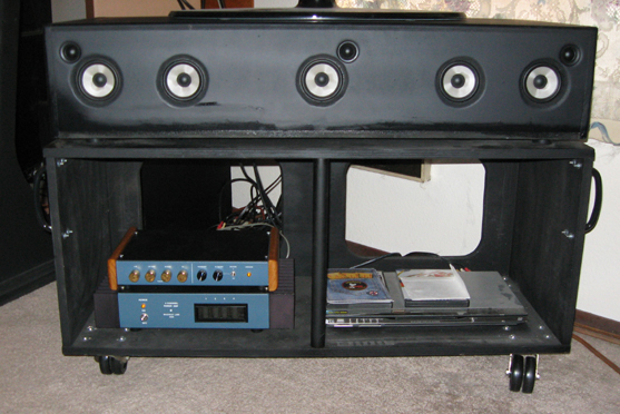
This was meant to be a one-box does it all replacement for a center channel speaker. The box has a total of 10 speaker drivers; 2-6.5 inch woofers on the sides, 5-3 inch drivers across the front, and 3-3/4 inch dome tweeters spread out across the front. It's designed to sit under a 42 inch TV set, and run by itself or as a center speaker in a multi-channel surround sound setup. The inputs are line level, not speaker level. It's more optimized for music than movies that have discrete steering of special effects (a plane flying overhead). It does have the option to separately drive the center driver from an external source, which may be preferred for movies. A pre-processor chassis has a 4 pole active Linkwitz-Riley crossover network, active woofer EQ, and a 4 section Baxandall tone control circuit (Lo, Mid-Lo, Mid-Hi, and Hi). It drives a 4 channel power amp (4 X 50 watts RMS into 8 ohms), which drives the speaker cabinet. The cabinet has passive L-XR wiring (to turn a 2 channel feed into 3 channels), and the Polk method of creating an acoustic hologram. The speaker system is 3 way, with crossovers at 150HZ (4 poles active) and 7kHZ (1 pole passive).
How Does it Work:
The Polk-style hologram effect worked very well, and possibly better than the Carver electronic approach for cancellation of inter-aural crosstalk. its weakness is that the 3-inch drivers just don't have enough cone surface area to handle frequencies down to 150HZ at reasonable sound levels. This is largely due to the baffle step effect, and the fact that the signal is split up with a passive matrix circuit such that a mono signal is reproduced primarily by just the center 3-inch driver, rather than all five at equal amplitude. There is some mono signal delivered to the outer drivers, but at about 6dB down. I eventually decided this project was not up to par and was just a valuable learning experience. I pulled the drivers and got rid of the cabinet. The crossover and power amp are now being used in a different system. But here are the details anyway, for those who might be interested.
The cabinet is 39 x 16 x 8 inches. Any bigger would be very difficult to move around.
David Griesinger, formerly of Lexicon, and an expert on recording techniques and acoustics says in his many papers on his website that typical listening room acoustics and inter-aural cancellation cause a decrease in perceived separation as you go down in frequency below about 1kHZ. I knew about the inter-aural cancellation issue but didn't realize that typical listening room acoustics also decrease our perception of stereo effects. One of the papers on his website shows a circuit for combatting that by decreasing the amount of L+R relative to L-R as you go down in frequency. It's a bandwidth-limited stereo matrix circuit. His papers led me to believe that the further down in frequency you go, the more important it is to have true stereo and good separation and that one of the most effective ways to improve the performance of a playback system is to do something about these mechanisms. This led me to think that I should wire my woofers in stereo (after decades of doing bass in mono, as it is on 95% of all CDs that I've listened to). I figured that putting the woofers on the ends of the cabinet (going from 30HZ up to 150HZ) would help this effort. I'd likely get a good sense of separation, both from interactions with listening room acoustics and especially when a recording has recorded the bass frequencies in stereo.
I've never heard the somewhat current version of the Polk soundbar. It might be better than what I've created. But all the Polk soundbars are designed to be wall-mounted and have a separate woofer box somewhere down on the floor. In my case, I'm out of room for any more woofers on the floor, and I prefer to have my TV on a stand on wheels so I can move it around or change its angle, depending on where in the room I am sitting (couch vs fireplace in my case). A cabinet that goes under the TV would need to be about 16 inches deep, and can comfortably be 39 inches long (with my 42 inch TV), so now there are room for two 6.5 inch woofers to be in that cabinet in addition to the five 3 inch drivers.
The Build:
The front, back, and dividers are 1/2 inch MDF, the center panel inside is 3/4 plywood, the ends are 3/4 inch MDF and all bracing is oak.
I glue and clamp in steps, and give it a full 24 hours minimum before removing the clamps and continuing.
Gluing and painting must be done outdoors due to the fumes. The wood glue (similar to Elmers) doesn't seem to have any harmful fumes, so I did all of that indoors.
I glued in the padding (and foam rubber - see below) with liquid nails glue.
The oak bracing being glued and clamped above helps reduce inner panel vibration, and also gives the screws that hold the bottom on something more reliable to anchor into. The edge of plywood or MDF can strip out pretty easily.
I chose the $65 Nomex cone (a variation of impregnated paper) Peerless drivers for woofers. They appear to be quite excellent. Very well vented spiders and relatively long-throw voice coils.
Since the 6.5-inch woofers may be the most likely thing to ever get blown, I decided to go to the trouble of making them replaceable without having to pull the bottom of the cabinet off (which is glued on with silicone rubber glue and has about 35 screws).
Also because the woofers are not capable of being rear-mounted because of how their flange is designed. It gets too skinny in certain places for a reliable airtight seal.
Rather than using the mounting holes on the frame of the 3-inch drivers (too close to the edge of the MDF baffle hole), I used fender washers and screws to hold them tight to their holes.
These Dayton 3/4 inch dome tweeters are apparently ruler flat from 4kHZ on up to 20kHZ according to Zeph (he used them in a 3-way speaker he built).
I use them above 7kHZ where the psycho-acoustic effects are such that you no longer need or want the hologram function to be active.
They are not part of the hologram function and don't need to be, they are just wired left, right and center.
I took the time to test each driver for obvious damage before installing them since replacing them later would be a royal pain.
You can see the bead of silicone rubber glue around the flange of the 3-inch driver (above) just before mounting it. Fitting a screwdriver into that small space to screw in the drivers from behind could have been a nightmare if I didn't have a short-handled screwdriver.
Even then it was difficult.
Below is a woofer chamber with oak bracing and glued in padding.
You can see how well vented the spiders are on the 6.5-inch Peerless woofers above. I used 16 AWG AC line cord wiring bought at any hardware store throughout. It's very cheap and just as good as anything for this purpose.
Above is the inside of the back of the cabinet, where all the banana jacks are.
The four woodblocks hold the passive crossover (below) above the banana jacks.
I color-coded each wire as I installed it with various sharpy pens, so I wouldn't get them mixed up when I connect them to either the crossover or the binding posts directly (in the case of the woofers).
You always want to keep air-core inductors away from each other. As shown is barely far enough apart.
The caps are all polypropylene 1 uF 250V. Cheap ones are fine. All five of the 3-inch drivers are rolled off above 7kHZ by the inductors.
I have cats, so I needed to protect the woofers. The cats crawl right past the woofers on their way into the window behind my TV. I got the metal grill at a nearby ACE hardware store.
The 3-inch drivers have such a minimal flange and acoustic clearance on the backside, I decided to rear mount them. This meant routering the holes with a 1/2 inch radius router bit to minimize acoustic impedance issues (cavity effect).
The tweeters required rear mounting too, so I needed to make the bottom of the cabinet removable in the event of a blown driver. Removable and yet acoustically very solid and vibration-free.
The tweeters are metric, so are designed to rear mount in a board that is about 1/16th of an inch short of half-inch... so I had to sand the 1/2 inch MDF down right where the tweeters would be mounted.
It's very important to do this well since any acoustic impedance irregularity here will color the sound of the high treble.
Before gluing the bottom one, I just screwed it on and listened to the system that way for a few weeks, just to be sure everything was right.
Foam rubber is actually a great acoustically absorptive material. With the denser padding underneath it, the end result approaches gaussian and is thereby very effective at dissipating in box resonant energy.
The chambers for the 3-inch drivers are very close to being cube-shaped, which is one of the worse shapes you can have acoustically, so damping had to be done the best way possible.
The pole pieces on the 3-inch drivers are vented, so you don't want to block those vents with anything firm.
The bottom is screwed on with 35 #10 pan head black wood screws and all edges have silicone rubber glue. It would be difficult to get the bottom off, but it is possible (I think). The pink stuff is regular foam rubber (bought at Fred Meyers hardware department). The gray padding is upholstered padding I bought at a place that refurbishes vintage car seats. It was only $10 for a square yard and works very well. Gluing the padding to the panel surfaces is very important. It's much more effective than if it's just stuck in there loose. The white stuff is the synthetic acoustically absorptive stuff you can buy at Parts Express in Indiana (or is it Ohio?). It's a very low mass, so not very effective at the lower frequencies. It makes a nice top layer over the padding and foam rubber. Organic materials like cotton can grow mold or bacteria over time. Better to use synthetic (some variation of plastic) material for acoustic padding.
Here's the module that plugs onto the banana jacks on the back of the cabinet. I used the vector board because it was there and served the purpose. Solid polyglass would be more durable. This is where the passive stereo matrix circuit and hologram wiring is.
I built it with an option to drive the center speaker from an external source, which might be better for some special effects movies. I doubt if I'll ever use it. The other switch is an on/off switch for the hologram drivers. Mostly there for demo purposes. The extreme right-hand hologram driver needs to get a feed from the other channel, which must be phase reversed, and then be knocked down by about 4-5dB, and vice versa for the other channel hologram driver, for the hologram effect to work. So I've got 5 ohms in series with each hologram driver for the 4-5dB drop, and 14.3 ohms across the center driver as a fine-tuning of the levels and L-XR effect. I had started with 10 ohms, based on calculations, but the center image seemed too dominated by the outer images. I think it's just right now.
The rear of the cabinet before the module is plugged on.
The power amp:
The power amp is four channels of LM3886 analog chip amps made by NS (or is it TI now?). I designed the circuits after much research (Linkwitz uses them in his Pluto system), and laid out the boards with the expresspcb.com free software (or was it PCB express - I can never get that right), and had them make the boards. I have a separate ground return for the big filter caps on each amp board to minimize hum. The 0.1uF bypass caps across those large caps are tied to the amp board circuit ground which is used by the rest of the parts, rather than the separate ground return wire for the big caps (for even lower hum and distortion). The chassis in both units are Hammond aluminum. The toroid is from Toroid.com in Maryland. I put in +/- 15 volt T0-220 regulator chips for the peak level indicator boards. I have no complaints about this amp. 50 watts RMS per channel into 8 ohms is enough for me. Some would want more. The 3-inch drivers are only about 85dB 1 watt at a meter, so they do eat power more than most. 88-90dB is more typical of Hi-Fi drivers. If I want really high volume, I turn on the rest of my 1/2 circle of surround sound system, at which point I have about 890 watts RMS in the room.
The circuit above is what I ended up with after testing it on the bench, looking closely at the phase margin (tendency to oscillate).
Above is my SPICE model, rather than the actual circuit. See "not shown" notes above for the difference.
There was a slight spurious oscillation as it came out of clipping on the negative half cycle, which L1, R9, C3, R4, C5, and R7 minimized.
The output choke is just 22AWG enameled wire wrapped around the body of the 5 watt 10 ohm R9 resistor, end to end.
The actual inductance value is not critical. I seem to remember mine measuring about 2uH actual.
The output filter, R9, and L1 are to reduce the reactance of the load at Rf frequencies, as seen by the 3886, so the circuit is less likely to oscillate.
Below is an amp board up close with the 3886 chip installed. Don't solder the chip onto the board until everything is physically mounted in the chassis and onto the heatsink.
Then just tack it in with two leads (one at each end), then remove the whole thing and (re) solder all the leads, then re-install it. One at a time.
High stress on the part of leads is said to be bad over time. This is how you minimize that.
A different PCB might require different anti-oscillation part values.
It's always wise to look closely at how any amp handles clipping on an oscilloscope.
Many power amps that I've looked at have some spurious oscillation as they come out of clipping.
I'm not generally a fan of putting some of the parts on the bottom of a circuit board, but for stability reasons (phase margin) some parts need to be as close as possible to certain nodes.
I tried several variations of phase margin compensation on this circuit until I got the best one.
This is where most power amp builders drop the ball. Spurious oscillations will give you the very "transistor sound" that the tube guys are trying to get away from.
Plus supersonic oscillations can burn out tweeters, and in extreme cases cause the power amp to blow up, and take the speakers with it.
It's not enough to look at square waves. I've found that spurious oscillations are often more likely when the amp is driven slightly into clipping.
One-half cycle or the other may have a bit of spurious oscillation as it comes out of clipping (it did in this case).
This (phase margin) is arguably the most important thing to know about and verify in any amplifier project.
The Pre-Processor:
Consists of a 4 section Baxandall tone control circuit, a 4 pole Linkwitz-Riley active crossover, an active EQ circuit for the woofers, some active baffle-step compensation for the 3-inch drivers, and a power supply.
Due to the low efficiency and weak low end of the 3-inch drivers, I decided to whip up a circuit board that would give me a gain of about 8dB, and provide some active baffle-step compensation.
All caps are Polypropylene except PS bypass. All R's are 1% metal film for minimal noise.
The On/Off switch for the processor is on the back to reduce hum, and since I just leave it on 24/7 anyway.
All of these boards were designed by me for a different project, which over time evolved into this project.
On the tone board, I didn't use the output level control buffer, so you can see an empty IC socket.
I did that function on the board to its right, where I wanted separate level controls for each frequency band, and some baffle step correction.
Above: In the upper left we have the 4 poles Linkwitz-Riley 150HZ crossover.
To its right, we have the active woofer EQ to make it somewhat acoustically flat at the listener position down to 30HZ.
Below those are the tone control board and the output level and baffle step board. On the right is the power supply.
Here you can see the L-XR and Hologram function module plugged onto the back of the enclosure.
The woofers are driven straight from the power amps. The upper band signals (above 150HZ) go through this module.
There are tone controls on the left, and output level controls for the bi-amp function on the right.
The upper band has a phase switch. I can't hear a difference so far but maybe the calibrated mic will show that it makes a difference.
I built the lower cabinet with wheels so I could aim it over at the fireplace, where I often sit for much of the year. Oregon's rainy season can be a bit gloomy.
The Circuits:
I'm driving this from the stereo line outs on my Stereo Receiver.
I don't know if Polk includes the L-XR function in their soundbar speakers. I've never seen any of their schematics. If different drivers are used, the above values would all be off a lot.
I never did get very good at Laplace Transforms (the s plane, where the square root of negative one lives). but I was taught how to scale part values in an existing circuit, to get the characteristics I want.
Above is the PSPICE model of the 150HZ Linkwitz-Riley 4 pole crossover network (no EQ included) (Graph not shown).
Above is an adaptation of the active woofer EQ circuit from an M&K Volkswoofer 3B (1982). It's a "Laverne-Traverse" topology (sp?), that I've messed with to get what I want (their peak was at 23HZ and closer to 20dB).
The great feature of this topology is that it rolls off fairly steeply below the frequency you want the woofer to peak at, so you are much less likely to "bottom out" the woofer with energies you don't need or want.
The 5K trim pot I included on the circuit board layout adjusts the height of the peak, relative to the upper frequencies (150HZ in this case). In the graph, it's set to zero ohms.
The peak is at 33.98HZ. I'm pushing my luck forcing a 6.5-inch woofer to be somewhat flat down to 30HZ at the listening chair, but I don't play my stereo very loud anymore, and it sounds VERY good.
Below is the phase, gain, and baffle step EQ I put on the upper and outputs in the pre-processor chassis.
I didn't need to use the more part-intensive circuit to roll off below the peak, since the upstream crossover board does that for me.
The power supply is nothing fancy. The 1M resistor across the primary of the toroid is to lessen the turn-on transient due to stored charge in the core (that's how Linkwitz does it). How grounding is done is the real trick.
If I had it to do over again, I would use bigger drivers on the front that could better handle the amount of baffle step correction that was needed. I'm very glad I included the 4 section Baxandall tone control circuit in the pre-processor chassis.
It was a valuable learning experience.
I hope this is helpful to my fellow hobbyists.