Your Legal Resource
Distortion Spectrum Shape
The MusicBox Tube Hi-Fi Power Amp
by Robert B. Richards A.E.
Test Results 11-10-07
Input signal: 400 HZ ultra clean sinewave from a Tektronix SG505 Generator
Output Load: 8-ohm resistor
Measurement Devices: Hewlett Packard 3585A Spectrum Analyzer and
Tektronix AA501A Distortion Analyzer.
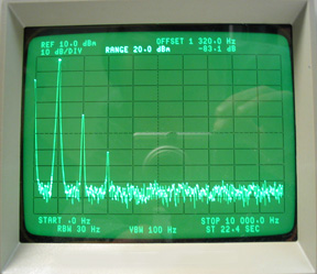
[ pic ]
Triode Mode, 3 watts rms, No feedback.
[ pic ]
Triode Mode, 6 watts rms, No feedback.
[ pic ]
Ultralinear Mode, 3 watts RMS, no feedback
[ pic ]
Ultralinear Mode, 6 watts RMS, no feedback.
Pretty dam good.
The 2nd harmonic is at -26.4dB down from the fundamental, and the 3rd harmonic is at -39.7dB.
Measured 4.7% THD on the AA501A, but all but 1% of that was the 2nd harmonic. No BW limiting filters were used.
[ pic ]
Ultralinear Mode, 3 watts RMS, feedback at mid (approx 8 dB).
This is arguably ideal. There's 1% 2nd harmonic distortion, but only 0.1% 3rd harmonic, and nothing significant after that.
[ pic ]
Ultralinear Mode, 6 watts RMS, feedback at mid (approx. 8 dB).
Less ideal.
Measured 1.3% THD on AA501A w. no filters engaged.
Conclusions:
- Somewhat to my surprise, ultra-linear mode with no feedback looks the best. It also causes the highest output impedance as seen by the impedance-sensitive passive crossover network at the speaker. That will have to be looked at closely.
- The ultra-linear mode seems to have less extension of harmonic distortion products away from the fundamental relative to the triode mode at 6 watts and no feedback. Could this be from the current sources which may have high feedback amplifiers inside them? Doesn't look like a big problem.
- The good news is that the 2nd harmonic is always higher than the third, and there's generally a quick roll-off of harmonic distortion products after that.
- It doesn't take much feedback to cause harmonic distortion products to extend pretty far out from the fundamental. See the last photo above.
- Now I've got a 30-watt RMS per channel amp with a good distortion spectrum shape, that is particularly good at driving the reactance of a speaker with minimal likelihood of generating slewing-related distortions. I'll have to compare it with Matt Kamna's SE GM70 amp and see if there's any audible difference.
Other measurements:
Power supplies:
At the 120VAC line, the current draw is 1.64 amps and 170 watts.
The 6F8G input tube has DC filament voltage, the rest have AC. All filaments are at 6.2 volts DC or RMS.
B+ = 403 VDC no signal. 393VDC with one channel at clipping.
The lower B+ means less power out, but it also means we can run the EL34's with a more quiescent current (closer to class A) without exceeding the power dissipation rating of the tube. Tentatively I've got the EL34's set at 45mA each. I'll take another look when I get a chance, and see how far from the power dissipation limit I am.
Gain of 6F8G stage:
Channel 1 = 30vpk / 3.25v pk = 9.23 or 19.3dB
Channel 2 = 32v pk / 3.25v pk = 9.85 or 19.8 dB
6F8G Bandwidth:
With Rf filter on input = 62kHZ.
Without Rf filter on input = 750kHZ.
Gain of 6SN7 diff-amp stage (no feedback):
Channel 1 = 15v pk / 1.8v pk = 8.33 or 18.42 dB
Channel 2 = 15.5v pk / 1.8v pk = 8.6 or 18.7dB
Triode mode Voltage Gain of
6SN7 (no feedback) > EL34 stage > output transformer > 10 ohm load resistor (6F8G stage excluded):
=3.95 or 11.9dB.
Triode mode Voltage Gain of
EL34 > transformer > 10 ohm load
= 0.45 or -6.85dB, relative to the voltage swing at only one EL34 grid.
Triode mode gain of whole amp (see note at bottom of page):
no feedback =15v pk / 0.35v pk = 42.8 or 33dB.
max feedback = 15v pk / 1.75v pk = 8.6 or 18.7dB.
22 dB was the goal, but not at all critical.
Gain differential due to feedback = 14.3dB
Power Out into 8 ohms:
16 W RMS in Triode mode
31 W RMS in Ultra-Linear mode.
The 70 HZ one pole highpass filter cap at the input effectively doubles the power (at least) available from this amp (below that is handled by a separate woofer system with its own power amp).
The bandwidth of the whole amp:
Low end (without the 70HZ highpass filter):
-3dB at 10 HZ. Waveshape was pretty distorted.
At 20 HZ waveshape distortion is more reasonable.
High end (no feedback):
-2.5dB at 40kHZ, -3dB at 67kHZ, and -6dB at 103kHZ.
(God was on my side).
Ultralinear mode had a bit more ringing on the square wave, about 1.5 minors with a 6 major division signal. Triode mode ringing was better damped to within a minor div with a 6 major div signal.
The output impedance of amp:
Triode mode, no feedback = 3.4 ohms.
Triode mode, max feedback = 0.8 ohms.
Ultra-Linear mode, no feedback = 8.8 ohms
Ultra-Linear mode, max feedback = 1.4 ohms
As you can see here, the calibration of the passive crossover at the speaker will be messed with significantly by these output impedances. Virtually all crossover designs assume a zero ohm source impedance. In a one-pole crossover, the poles would be moved down in frequency, but not by the same amount. This is due to the changed circuit impedance differentials, as viewed by the reactive crossover components (cap and coil) at the crossover frequency between the tweeter and the midrange drivers. The tweeter in my case is 7 ohms and the mids are 13.5 ohms at 3.5kHZ. With a higher-order crossover (2 poles and above), the curve shapes would be thrown off even more, which could get pretty ugly.
You've got to pick a mode and feedback amount (triode mode with 7dB of feedback, for example (2.1 ohms)), before trying to calibrate the crossover. Other modes and feedback amounts then get labeled "experimental" since they will somewhat un-calibrate the passive crossover at the speaker system. This is one of the reasons why it's hard to do a fully valid listening comparison.
Gain differential of Triode mode vs. Ultralinear mode:
U.L = 34.9 dB (no feedback), Triode = 30 dB.
Differential = 4.9dB
Note: Since minor mods that affected gain were done during testing (a 33K ohm was added from 6F8G grid to ground to reduce impedance and thereby hum), the numbers closest to the bottom of this list are to be considered more final, if there's any discrepancy.