Your Legal Resource
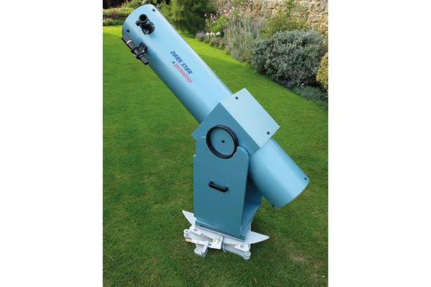
20.5" F5.4 Motorized Dobsonian Telescope
Dobsonian telescopes are popular instruments. They provide large apertures for a reasonable price and as such is suited to observing faint, deep-sky objects. Their wide optics can also cope with high magnifications, but it can be tricky to keep celestial targets centered in the field of view in this situation, especially if � as is most common � your Dob has a manually operated altaz mount.
Tools � Jigsaw, router, hacksaw, drill and bits, plane, spanner, Allen key, screwdriver
Materials � 1,200x600mm sheet of 18mm plywood (this is enough for parts one and two of this project), 1m length of 30x30x2mm aluminum angle, 1m length of 12x2mm aluminum strip, A3 sheet of thin polycarbonate plastic or similar, 600x40x30mm offcut of wood
Sundries � Eight 608ZZ skateboard/rollerblade bearings (22x8x7mm), eight M8x25 socket head screws, eight M8 washers, 16 M8 nuts, woodscrews, wood glue, double-sided tape
Finish � Wood varnish or spray paint
----------------------------------------------------------------------------------------------------------------------------------------------------------
Step 1
After separately weighing your telescope and mount/base, balance the base on an offcut of the tube to find its center of gravity.
Calculate the combined center of gravity using the spreadsheet calculator included in the folder here.
Step 2
Use the calculated values and plans to mark out the segments you need on the plywood.
Cut the arcs first with a jigsaw.
Don�t cut the segments away from the board until you have finished smoothing the arcs.
Step 3
If you have a router you can attach it to a radius rod with a pin at the center.
Take multiple shallow cuts until you have reached a smooth curve (allow for the thickness of the aluminum bearing strip).
Once satisfied, cut out the segments and remaining parts.
Step 4
Assemble the plywood parts with glue and screws.
Sand and paint to suit your tastes.
Cut some thin polycarbonate and stick to the undersides of each segment.
Cut aluminum bearing strips to length and fix them to segment edges with a small screw at either end.
Step 5
Mark out and cut the aluminum angle sections.
Use a smaller pilot drill first and then switch to an 8mm drill for the larger holes.
Hold pieces safely in a vice or clamp when drilling.
Shape the wooden blocks using a plane or saw set to appropriate angles.
Step 6
Screw the north bearing assembly to the remaining plywood, which will become the baseboard.
Ascertain the best position for the south bearing and fix it with a central pivot screw.
Use packing under blocks as necessary to level the top when centered.
Step 7
Now we�ll show you how to complete and motorize the Dobsonian equatorial platform.
We have documented our build with downloadable photographs available from the link at the top of this article so you can replicate the parts, but because your choice of the drive motor and power supply could differ according to circumstances and availability you may have to adapt the design a little to suit your kit.
Our spreadsheet calculator (also at the link) once again comes to the rescue when it comes to working out gear ratios so all you need to do is input your values and experiment with the numbers until the ratios match your needs.
Step 8
Use the spreadsheet calculator in the downloadable materials to select appropriate gears.
If your gearbox motor turns at 10rpm or slower, you will probably only need a worm and wheel.
The wheel turns the output shaft, which drives the north segment.
Step 9
Make a gearbox using offcuts of the aluminum angle.
Mark and drill holes accurately so shafts turn freely and without any play.
Use M3 screws and nuts to hold it all together.
A small output gear on the outside will drive the segment.
Step 10
Use a strip of modeling clay and the output gear to create a profile for the rack.
Put a taller strip of wood on either side and fill the gap with hot glue.
Once this has cooled, you can wash out the clay to reveal a plastic rack.
Step 11
The gearbox is fixed to a short arm.
The arm pivots on a piece of the angled bracket, which is screwed to a raised plywood support so that the drive gear can mesh with the rack when engaged.
This is a bit fiddly, so spend time refining the position.
Step 12
Mark around the bearings and arm support to draw a suitable shape for the base.
Cut this out with a jigsaw.
Make three jacking screws from M8 coach bolts with captive nuts pressed into holes in the underside of the base.
Paint to match the platform.
Step 13
Assemble all the parts and check to see everything is moving freely and the gears are engaging.
Solder wires to the motor terminals and connect to the controller, which should be protected in a suitable case.
Connect the power.